
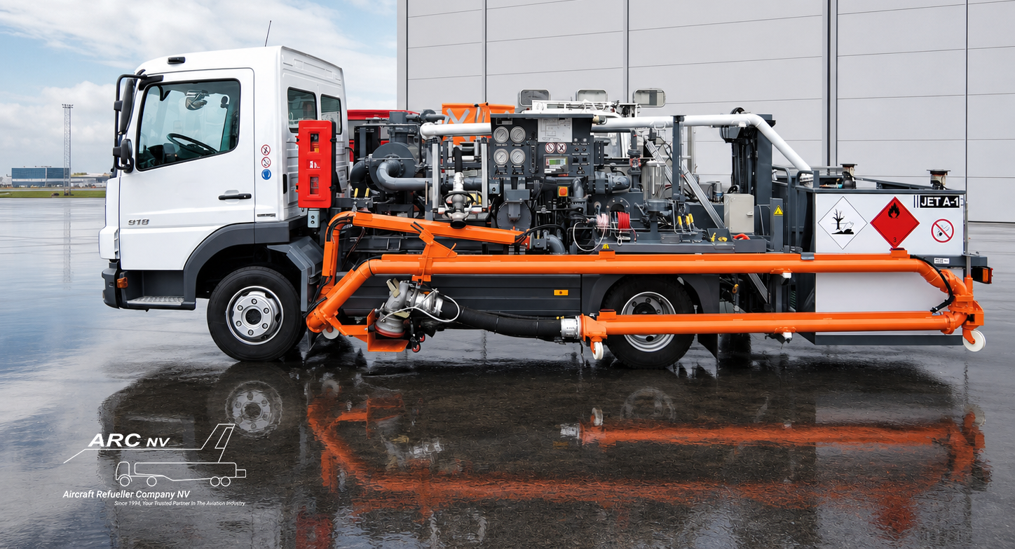
Airport Fuel Hydrant Systems: Design & Operations | ARC NV

Airport Fuel Hydrant Systems: Design & Operations | ARC NV
Every minute an aircraft remains on the ground can affect airline schedules, stand availability, airport capacity, and operating costs. As airports handle increasing traffic and higher fuel demand, aviation fuel must be delivered efficiently without compromising fuel quality, apron safety, or operational resilience.
An airport fuel hydrant system provides a fixed infrastructure solution for transferring aviation fuel from the airport fuel facility to designated aircraft parking positions. Instead of relying entirely on tank refuellers to transport fuel across the apron, the fuel moves through a pressurised underground pipeline network to hydrant pits installed at designated aircraft stands.
Hydrant systems are an established solution at many medium and large commercial airports. They can reduce the movement of loaded refuellers, support high-volume aircraft fuelling, and provide a scalable distribution network. Their effectiveness, however, depends on much more than buried pipework.
System architecture, hydraulic capacity, pressure surge control, pipeline integrity, hydrant pit positioning, fuel quality, emergency shutdown, maintenance access, and the hydrant dispenser must operate as one integrated system.
This article explains how airport fuel hydrant systems work, their principal components, the aircraft hydrant fuelling process, the role of the hydrant dispenser, and the design and lifecycle controls required for long-term performance.
What Is an Airport Fuel Hydrant System?
An airport fuel hydrant system is a fixed aviation fuel distribution network that transfers fuel under pressure from airport storage and pumping facilities to hydrant pits located near aircraft parking positions.
The principal system boundary and ownership arrangements can vary between airports, but the wider infrastructure normally includes:
- Aviation fuel storage tanks
- Hydrant pumps and pressure surge-control equipment
- Filtration and fuel quality systems
- Underground distribution pipelines
- Isolation and sectionalising valves
- Leak-detection and integrity-monitoring arrangements
- Hydrant pit valves
- Emergency shutdown
- Hydrant dispensers or hydrant servicing carts
The Energy Institute describes airport hydrant systems as the penultimate stage in the aviation fuel delivery chain before fuel reaches the aircraft. Fuel cleanliness and system integrity must therefore be maintained throughout operations, inspections, maintenance, shutdowns, and recommissioning. EI 1560 addresses these subjects for hydrant-system owners, operators, and designers.
How an Aircraft Hydrant Fuelling System Works
Fuel is transferred from the airport fuel facility by hydrant pumps into the underground distribution network. Pump controls, pressure-management systems, and surge-control equipment maintain suitable operating conditions as demand changes across the connected aircraft stands.
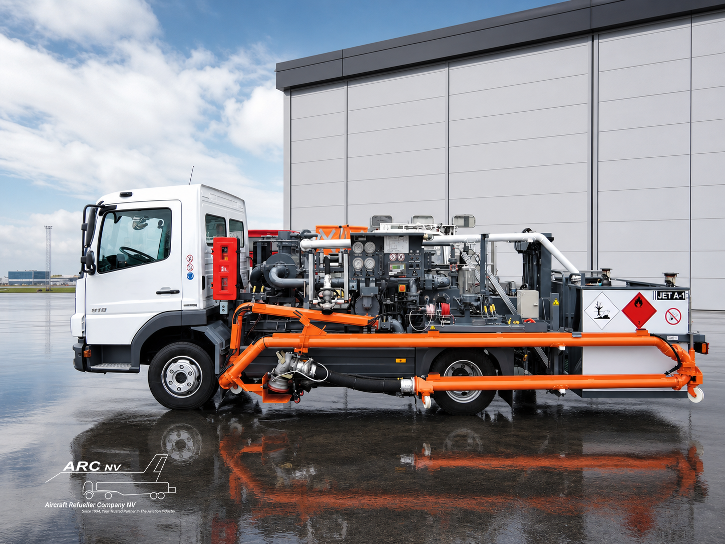
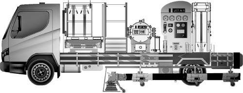
The fuel moves through the pipeline network to the selected hydrant pit. A hydrant dispenser connects to the hydrant pit valve and provides a controlled interface between the fixed airport infrastructure and the aircraft.
The dispenser receives pressurised fuel from the hydrant system and performs the functions required for safe delivery into the aircraft, including:
- Fuel filtration
- Quantity measurement
- Flow and pressure control
- Differential-pressure monitoring
- Bonding
- Deadman control
- Emergency shutdown
- Hose and aircraft fuelling-nozzle management
- Operator monitoring and control
Unlike a tank refueller, a conventional hydrant dispenser does not carry a large fuel tank and normally relies on the hydrant network to provide fuel pressure. This generally makes the unit lighter and more manoeuvrable than a loaded refueller, although the exact configuration depends on the operating requirement and equipment design.
Key Components of an Airport Fuel Hydrant System
Fuel Storage, Pumping, and Surge Control
The airport fuel facility must provide sufficient storage, pump capacity, and control capability to meet both routine and peak aircraft fuelling demand.
The hydraulic design should consider:
- Peak and simultaneous aircraft fuelling
- Minimum and maximum operating flow
- Pressure losses across the network
- Pump availability and redundancy
- Valve opening and closure
- Rapid changes in system demand
- Pressure transients and surge events
- Partial-system operating conditions
- Planned future capacity
A system may provide sufficient steady-state flow and still experience operational problems if pump transitions, valve movements, or emergency shutdown conditions create unacceptable pressure changes.
Hydrant pumps, pressure-control valves, surge protection, and dispenser pressure-control equipment must therefore be evaluated as parts of the same hydraulic system.
Underground Pipeline Network
The underground network distributes fuel to the apron and may consist of looped sections or branches, depending on airport geometry, operating requirements, expected demand, and investment constraints.
Looped arrangements can provide greater operating flexibility by allowing sections to be isolated while alternative supply paths remain available. They may also facilitate circulation, flushing, cleaning, maintenance, and future extension.
Branched or dead-end arrangements may require less initial infrastructure but can create greater constraints when downstream sections need to be isolated, flushed, cleaned, or extended.
No layout should be selected solely because it has the lowest initial cost. Its maintainability, cleanability, commissioning requirements, future capacity, and consequences of partial shutdown must also be considered.
Hydrant Pits and Hydrant Pit Valves
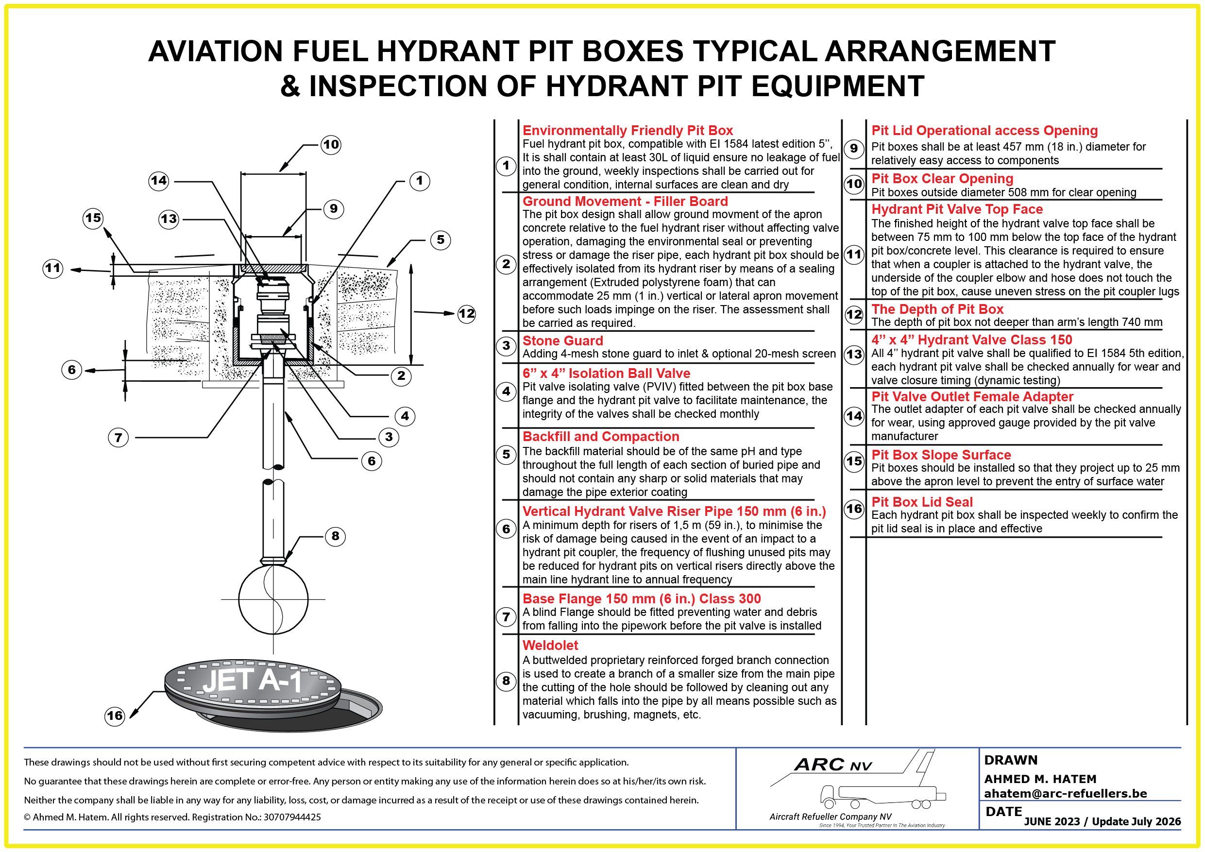
Hydrant pits form the accessible connection between the underground pipeline and the hydrant dispenser.
Pit positioning must consider:
- Aircraft types and stand configurations
- Final aircraft stopping positions
- Dispenser positioning and escape path
- Intake-hose reach and routing
- Aircraft engines, nacelles, and vents
- Passenger, baggage, and cargo activity
- Other ground support equipment
- Apron drainage and surface levels
- Aircraft and vehicle wheel loads
- Inspection and maintenance access
A poorly positioned pit can cause difficult hose routing, equipment conflict, restricted maintenance access, or unnecessary exposure to operational damage.
Pit boxes, lids, and valves must also withstand the conditions expected on the apron. The Energy Institute’s research into hydrant pit-box loading addresses the surface loads applied to pit lids and the need for suitable production testing to reduce the risk of in-service collapse.
Hydrant pit valves and pit couplers should meet the applicable requirements of EI 1584, which provides performance and mechanical specifications intended to support equipment compatibility and interchangeability. The current fifth edition was published in November 2025.
Monitoring, Isolation, and Integrity Protection
Most of the hydrant pipeline is underground and cannot be assessed through routine visual inspection alone. The system should therefore incorporate appropriate controls to detect deterioration, isolate affected sections, and maintain asset integrity.
Depending on the installation, these may include:
- Sectional isolation valves
- Pressure monitoring
- Automated or manual integrity testing
- Leak-detection arrangements
- Corrosion monitoring
- Cathodic protection
- Controlled drainage and product recovery
- Alarm and event recording
- Documented leak and loss investigation procedures
The selected arrangements should be based on the pipeline design, environmental conditions, local requirements, and the airport’s operational risk assessment.
Aircraft Hydrant Fuelling Process
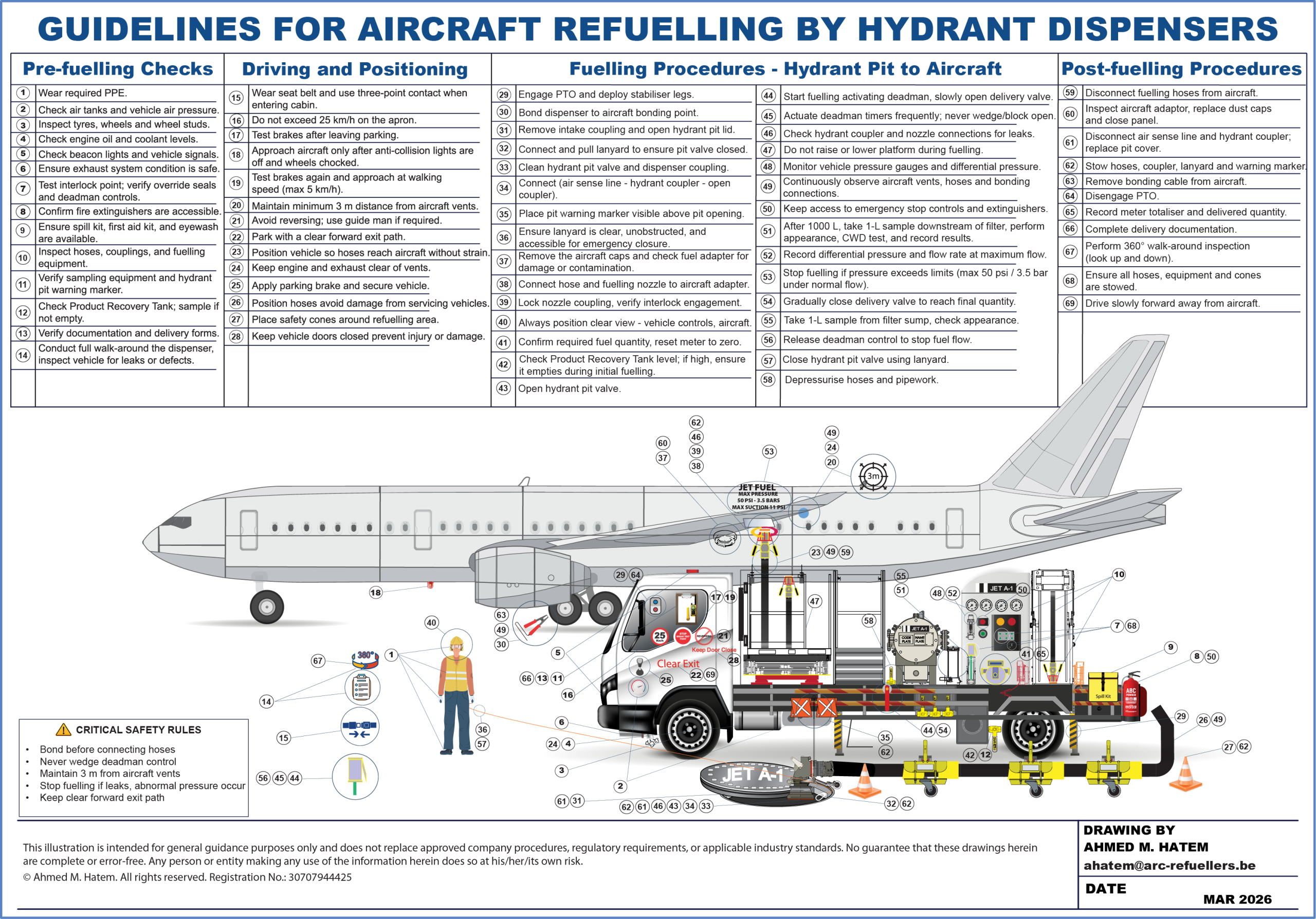
The exact operating sequence must follow the approved company procedures, equipment instructions, aircraft requirements, and applicable standards. A typical aircraft hydrant fuelling process includes:
- The aircraft is positioned and secured at a hydrant-equipped stand.
- The hydrant dispenser is positioned without obstructing other critical ramp activities.
- The operator completes the required pre-use inspection of the hydrant pit valve and the vehicle.
- The correct fuel grade, delivery documentation, and required aircraft uplift are confirmed.
- The dispenser-to-aircraft bonding connection is established.
- The intake coupling is removed from its stowage point and connected to the hydrant pit valve.
- The aircraft fuelling nozzle is connected to the aircraft fuelling adaptor.
- The operator verifies the condition and readiness of hoses, couplings, filtration, pressure controls, interlocks, deadman controls, and emergency equipment.
- Fuel flow is initiated under deadman control.
- Delivered quantity, flow rate, system pressure, differential pressure, hoses, connections, aircraft vents, and the surrounding area are monitored throughout the operation.
- Fuel flow is stopped when the required quantity has been delivered.
- The hydrant pit valve is closed, and hoses and pipework are depressurised as required.
- The aircraft nozzle, intake coupling, and bonding cable are disconnected in the approved sequence.
- Dust caps and covers are replaced, equipment is stowed, and the hydrant pit is secured.
- The delivered quantity and required documentation are completed.
Positive operator control must be maintained throughout the transfer. ARC’s article on Deadman Control in Aviation Refuelling explains the importance of continuous operator action and controlled fuel-flow shutdown. The article is included in ARC’s current technical news library.
Why the Hydrant Dispenser Is the Critical Interface
The underground pipeline provides the distribution network, but the hydrant dispenser is the operational and safety-critical interface between the hydrant system and the aircraft.
Its function is not simply to transfer fuel. The dispenser must control and verify the final delivery conditions before fuel enters the aircraft.
A hydrant dispenser may incorporate:
- Intake coupling and intake hose
- Fuel filtration
- Calibrated metering
- Hose-end and in-line pressure control
- Differential-pressure indication
- Thermal and pressure-relief arrangements
- Deadman control
- Emergency shutdown controls
- Bonding equipment
- Aircraft fuelling hoses and nozzles
- Sampling and fuel-quality provisions
- Vehicle interlocks and brake systems
- Elevating platform and operator controls
- Product-recovery arrangements
- Electrical and pneumatic control systems
The required configuration depends on hydrant pressure, aircraft mix, target flow rate, stand geometry, hose arrangement, and operator requirements.
ARC designs and manufactures aircraft hydrant dispensers around the pressure, flow, and uplift requirements of the actual airport operation.
Safety and Fuel Quality in Hydrant Operations
An underground hydrant system can reduce movements of loaded tank refuellers, but it remains a pressurised aviation fuel installation. Safe operation depends on appropriate engineering, controlled procedures, inspection, preventive maintenance and competent personnel.
The applicable compliance framework depends on the country, airport, fuel operator, aircraft operator, and authority having jurisdiction. Widely recognised industry references include:
- EI 1540 for the design, construction, commissioning, maintenance, and testing of aviation fuelling facilities
- EI 1560 for hydrant-system operation, inspection, maintenance, and commissioning
- EI 1584 for four-inch hydrant pit valves and pit couplers
- JIG standards covering aviation fuel operations across the supply chain
- The applicable edition of NFPA 407 for aircraft fuel-servicing fire-safety requirements
EI 1540 provides industry guidance for the design, construction, commissioning, maintenance, and testing of new, modified, and extended aviation fuelling facilities, including aircraft refuellers, hydrant dispensers, hydrant maintenance vehicles, and associated equipment. EI 1560 focuses specifically on hydrant-system fuel quality, cleanliness, commissioning, inspection, and maintenance.
Important operational controls include:
- Fuel cleanliness and water control
- Filtration and differential-pressure monitoring
- Hydrant pit and pit-valve condition
- Hose, coupling, and seal integrity
- Pressure-control performance
- Deadman functionality
- Emergency shutdown functionality
- Bonding continuity
- Vehicle interlocks
- Leak identification and reporting
- Preventive maintenance
- Controlled return to service
- Competent operators and maintenance personnel
- Traceable inspection, test, and maintenance records
ARC’s Aviation Refuelling Standards article provides a wider context on the standards that influence airport fuel operations and equipment.
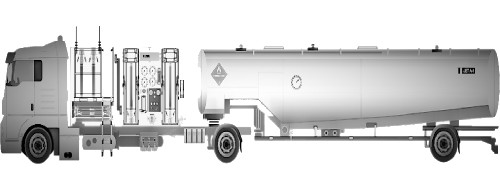
Hydrant Fuelling vs Refuelling Trucks
Hydrant systems and tank refuellers each serve valid operational requirements. The correct selection depends on airport demand, stand layout, traffic pattern, resilience requirements, and lifecycle economics.
Potential Advantages of Airport Fuel Hydrant Systems
A properly designed hydrant system can provide:
- Reduced movement of loaded refuellers across the apron
- Less congestion around frequently used aircraft stands
- Continuous access to fuel without repeated depot-replenishment journeys
- Support for high and simultaneous aircraft fuelling demand
- Centralised distribution and integrity control
- Reduced mobile fuel inventory around terminal stands
- Potential reductions in heavy-vehicle fuel use and local emissions
- Greater scalability for high-volume operations
Infrastructure Responsibilities and Limitations
Hydrant infrastructure also introduces significant responsibilities:
- High initial capital investment
- Complex underground assets
- Specialist commissioning and cleanliness requirements
- Dependence on pump and pipeline availability
- Potentially significant consequences from system shutdowns
- Long-term corrosion and integrity management
- Specialist inspection and maintenance needs
- Reduced flexibility if future demand or stand layouts were not adequately assessed
Tank refuellers remain appropriate for smaller airports, remote stands, dispersed aircraft operations, contingency supply, defuelling, and locations where fixed infrastructure cannot be economically justified.
At many airports, the strongest resilience strategy is therefore a balanced fleet of hydrant dispensers supported by sufficient refueller capability for contingencies and non-hydrant operations.
Design Considerations for Underground Aviation Fuel Systems
Demand and Hydraulic Modelling
Hydrant-system capacity should be based on credible operational data rather than the number of aircraft stands alone.
The assessment should consider:
- Aircraft fleet mix
- Expected uplift by aircraft type
- Peak-hour demand
- Simultaneous fuelling operations
- Required delivery flow and pressure
- Pipeline pressure losses
- Pump availability and redundancy
- Partial-system operating conditions
- Future traffic and terminal expansion
Both undersizing and excessive oversizing can create operational and lifecycle problems. The system should support credible future demand while maintaining acceptable pressure, flow, and fuel-quality conditions.
Pressure and Surge Management
The hydraulic analysis must account for normal flow and transient events, including pump start-up, simultaneous demand changes, valve operation, and emergency shutdown.
Pressure surges can affect pipelines, pit valves, dispenser equipment, and aircraft fuelling conditions. Pump controls, surge-control equipment, valve closure times, and hose-end or in-line pressure-control systems must therefore be assessed together.
Clean Construction and Commissioning
Construction completion does not mean that a hydrant system is ready for aviation fuel service.
A controlled commissioning programme should address:
- Material and component control
- Welding and construction quality
- Internal pipeline cleanliness
- Pressure-strength and leak testing
- Flushing and cleaning
- Pigging, where applicable
- Dewatering and drying
- Controlled introduction of fuel
- Sampling and fuel-quality acceptance
- Documentation and handover
EI 1560 emphasises clean-build practices and robust commissioning as essential foundations for safe, reliable operation and maintained fuel quality. EI 1594 provides additional guidance where water is used for initial pressure-strength testing and subsequent dewatering and drying are required.
Maintainability and Lifecycle Planning
Maintainability should be designed into the system from the beginning. Infrastructure that cannot be isolated, inspected, cleaned, or repaired effectively will create operational exposure throughout its service life.
Lifecycle planning should include:
- Safe access to hydrant pits, isolation valves, drains, test points, and monitoring equipment
- Sectional isolation that limits the number of unavailable aircraft stands during maintenance or repair
- Defined arrangements for integrity testing, flushing, cleaning, pigging, and controlled product recovery
- Corrosion-control and cathodic-protection monitoring
- Critical spare-parts identification, stocking strategy, and component-obsolescence management
- Planned maintenance resources, specialist tools, and competent personnel
- Contingency fuel-supply arrangements for partial or complete hydrant shutdown
- Preservation, inspection, and recommissioning requirements following extended shutdown
- Provision for future apron, terminal, aircraft-mix, and fuel-demand changes
- Controlled drawings, valve schedules, asset registers, and inspection histories
- Formal management of change for modifications, extensions, and altered operating conditions
- Defined technical acceptance and return-to-service requirements
Lifecycle evaluation should consider availability, maintenance burden, integrity risk, and operational consequences—not only construction cost.
Future-Ready Hydrant Dispensers
Airports are increasingly assessing battery-electric and other lower-emission ground support equipment.
Electrifying a hydrant dispenser changes the vehicle’s propulsion, power, and control architecture, but it does not remove the need for fuel-system safety, bonding, pressure control, emergency shutdown, maintainability, and operational verification.
ARC’s article on Electric Refuellers & Hydrant Dispensers: EI 3618 Safe Deployment explains why electric refuelling equipment must be evaluated as a complete operational platform rather than as a simple replacement chassis.
Operating and Maintaining a Hydrant System
Long-term performance depends on disciplined operation after commissioning. Maintenance must preserve fuel quality, hydraulic performance, containment integrity, and the availability of safety-critical functions.
A robust operating and maintenance programme should address:
- Routine inspection of hydrant pits, pit lids, pit valves, and accessible equipment
- Confirmation that pits remain clean, dry, secure, and free from visible leakage or damage
- Fuel-quality surveillance, sampling, and low-point management in accordance with approved procedures
- Trending of system pressure, flow performance, alarms, and unusual operating behaviour
- Planned hydrant integrity testing and prompt investigation of unexplained pressure loss or product imbalance
- Functional testing of emergency shutdown, alarms, controls, and associated safety systems at defined intervals
- Inspection and monitoring of corrosion-protection and cathodic-protection systems
- Preventive and condition-based maintenance of pumps, valves, controls, monitoring equipment, and pits
- Clear defect classification, reporting, isolation, and out-of-service controls
- Availability of critical spares, specialist tools, and competent technical support
- Controlled planning and communication of partial or complete system shutdowns
- Preservation requirements during extended shutdown
- Defined inspection, testing, flushing, and fuel-quality acceptance before return to service
- Formal management of change for modifications, extensions, temporary arrangements, and revised operating conditions
- Initial and recurrent competency training for operators, inspectors, and maintenance personnel
- Traceable records of inspections, tests, defects, repairs, modifications, and return-to-service approvals
- Periodic review of performance trends, recurring defects, and lifecycle risks
Modifications and extensions should be subject to the same engineering discipline as the original system. Changes in demand, pipeline configuration, stand arrangement, valve settings, or dispenser design can affect the wider hydrant network and should not be assessed in isolation.
Conclusion
Airport fuel hydrant systems are a central part of aviation fuel infrastructure at many medium and large airports. They can support high-volume aircraft fuelling, reduce movements of loaded tank refuellers, improve apron organisation and provide a scalable fuel-distribution network.
A hydrant system, however, is more than underground pipework. Long-term performance depends on appropriate hydraulic design, surge control, clean construction, effective commissioning, suitable hydrant pit positioning, asset-integrity management, and disciplined operation.
The hydrant dispenser completes the system by performing the final filtration, metering, hose-end or in-line pressure control, bonding, deadman, and emergency shutdown functions before fuel reaches the aircraft.
Airport operators and aviation fuel providers should therefore evaluate hydrant infrastructure as a complete lifecycle system. Safety, fuel quality, operational demand, resilience, maintainability, and future expansion must be considered together rather than treated as separate design decisions.
Contact Us
Planning new hydrant-dispenser capacity, replacing aging equipment, or preparing for the electrification of your airside fleet?
ARC NV designs and manufactures aircraft hydrant dispensers for safe, reliable, and efficient airport fuelling operations.
ARC supports customers with:
- New hydrant dispenser design and manufacturing
- Conventional and battery-electric vehicle solutions aligned with EI 3618 safety justification
- Vehicle refurbishment and system upgrades
- Maintenance and repair support
- Vehicle inspection and lifecycle management
- Safety-system integration and serviceability improvements
Contact ARC NV to discuss your operational and equipment requirements.
Email: question@arc-refuellers.be
Telephone: +32 3 844 55 68

 Ravitailleurs
 Distributeurs
 Applications Militaires
 Pièces de rechange
 Entretien et réparations
 Remise à neuf de véhicules
 Contrôles
 Gestion du cycle de vie des véhicules

