The definition of hydrant dispensers’ specifications, the size of hydrant piping, and the number and capacity of the hydrant pumps are crucial activities.
ARC NV designs vehicles based on approved drawings including, – a flow diagram, general layout, fueling panel, and hazardous area. Understanding all facets of efficient and reliable aviation fueling facilities across full asset integrity awareness is essential to airport operations.
DISPENSERS OPERATIONAL REQUIREMENTS
Flow Rate Up to 4000 L/M
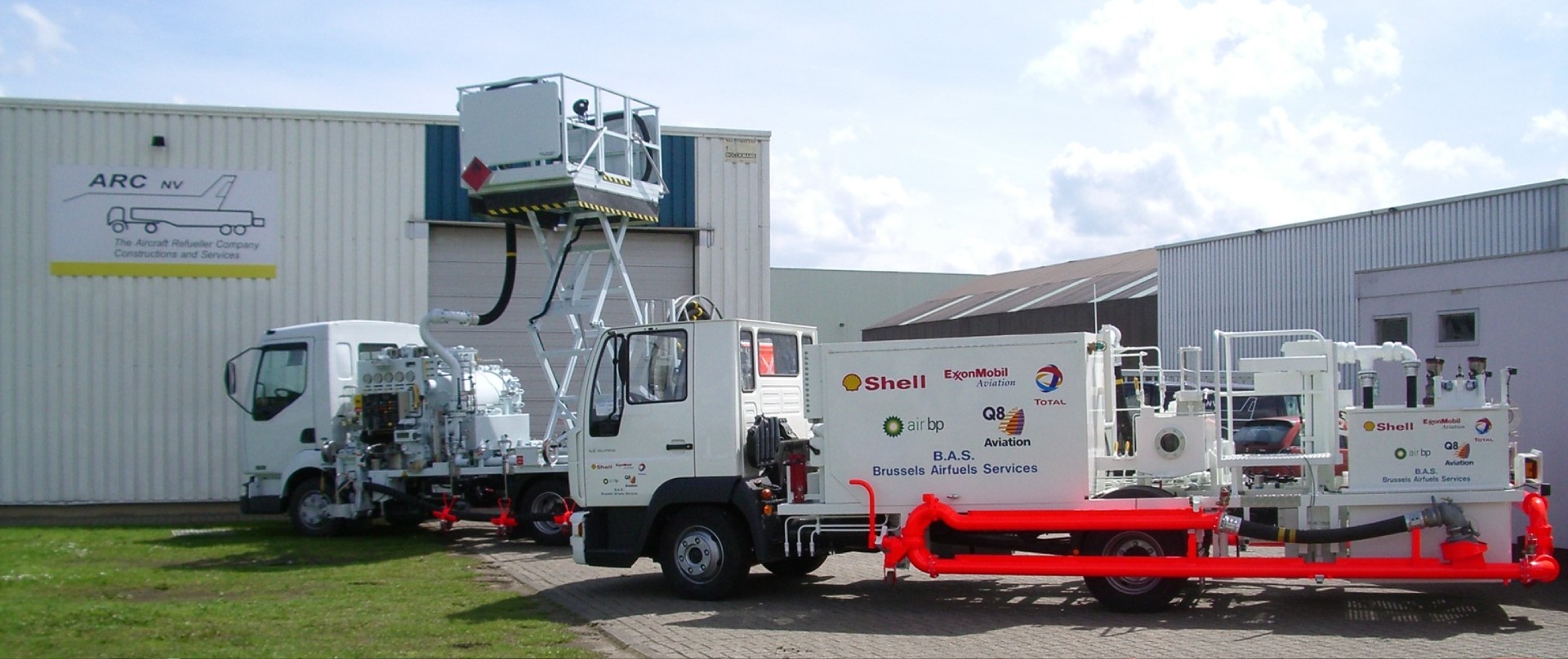
The hydrant dispensers are designed and built with an elevating platform to allow the operator to reach the underwing fuel couplings.
These dispensers also can-do standoff refueling, which usually occurs on aircraft with low wings, which the dispenser cannot park to accommodate this type of fueling. In addition to the deck hoses, the dispenser has a reel hose mounted on the chassis.
The hydrant dispensers are built and designed to suit the flow rate and pressures of the hydrant system. We also consider the size and uplift requirements of the aircraft that will need fuel in the design. These vary typically from 1500 liters per minute to 4,000 liters per minute.
The Equipment on the Dispenser Comprises the Following Basic Parts
Inlet Coupling (Incorporating a dead-man function)
Inlet Hose
Filtration
Meter
Meter Valves
Nozzles
Sampling Equipment
Pressure and Thermal Relief Systems
Deadman System
Control Station
Elevating Platform
Hose Reels
Hoses
Pressure Control Equipment
Electrics
Pneumatics
Safety Features
Equipment Configuration
ARC NVEngineering and construction of refueling / Hydrant dispensers focus on the highest priorities of performance opportunities ensuring that the full scope of the OEMS effectively implemented and cost-effective, making sure the operational requirements are met.


 Maintenance & Repairs
 Vehicle Refurbishment
 Vehicle Inspection
 Vehicle Life Cycle Management

